
Circular connectors are the backbone of industrial automation, automotive, aerospace, medical equipment, and audio-visual systems. When selecting circular connectors for wiring, signal transmission, and power connection projects, understanding the core differences between male and female circular connectors in pin layout, structural design, and application scenarios is critical to ensuring stable connection, operational safety, and long service life. Many engineers and purchasers confuse their pin arrangement rules and usage standards, leading to poor matching, signal failure, or even safety hazards. This guide fully compares male and female circular connectors, focusing on pin layout logic and practical application differences, helping you select the ideal connector for your project.
1. Basic Definition & Core Structural Differences
By global industry standards (IEC, MIL-Spec, UL, ISO), male and female circular connectors are defined by their contact structure, which distinguishes their fundamental functions:
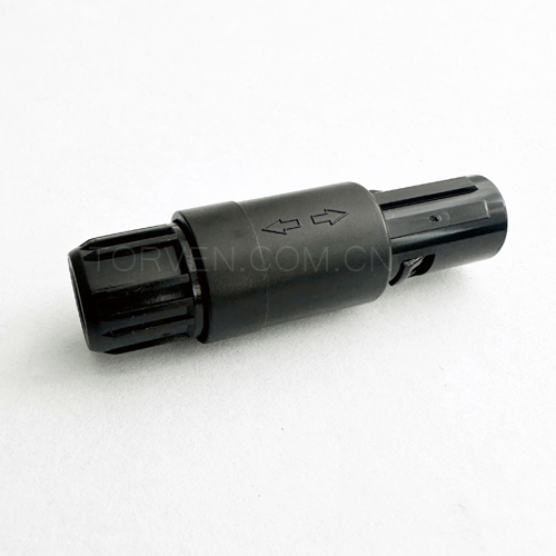
- Male Circular Connector (Plug): Features protruding, exposed conductive pins as the core contact part. It acts as the inserting terminal for mating connection, with external threaded or locking structures in most industrial models such as M8, M12, and M16. Male connectors are compact in contact structure and designed for plug-in active connection.
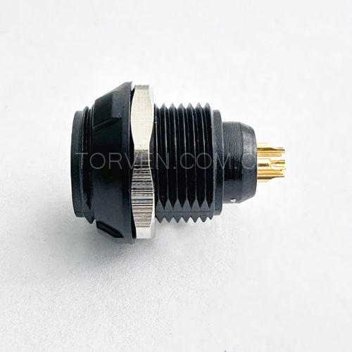
- Female Circular Connector (Socket/Jack): Equipped with recessed, enclosed socket cavities to receive male pins. Its internal protective structure shields contact points effectively, avoiding direct exposure of live parts. Most female connectors adopt internal thread design to cooperate with male threads for locking and fixing.
The most intuitive structural difference determines their pin layout rules and applicable working environments, forming a complementary mating relationship in circuit connection systems.
2. Pin Layout Differences: Male vs Female Circular Connector
Pin layout is the key technical distinction between male and female circular connectors. Although both follow unified pin numbering standards for compatibility, their viewing angles and arrangement logic are mirror designs, which is the main cause of wiring errors in actual operation.
2.1 Male Connector Pin Layout
For male circular connectors with exposed pins, the standard pin numbering rule is based on the front view of the plug end (facing the protruding pins). Starting from the positioning key or positioning notch, all pins are numbered in clockwise order. Common specifications including 3-pin, 4-pin, 5-pin, 8-pin M12 circular connectors strictly follow this rule. The pins are uniformly distributed in a circular array with equal spacing, ensuring precise docking and avoiding misalignment.
2.2 Female Connector Pin Layout
Female circular connectors adopt a mirror layout design. When viewing the socket end facing the recessed cavity, pin numbers start from the corresponding positioning key and are arranged in counterclockwise order. This reverse layout is to adapt to the plug-in direction of male connectors, ensuring that the pin circuit corresponds one-to-one after docking. Although the viewing arrangement is opposite, the electrical circuit definition of male and female pins is completely consistent, which guarantees universal mating compatibility of standard circular connectors.
2.3 Supplementary Technical Features
Both male and female connector contacts are made of high-conductivity copper alloy with gold-plated or tin-plated surface treatment, reducing contact resistance and improving oxidation and corrosion resistance. The difference is that male pins bear friction loss during frequent plugging and unplugging, while female sockets protect internal contacts from external dust, moisture, and mechanical damage.
3. Application Scenario Differences: Male or Female Connector to Choose?
Based on structural and layout characteristics, male and female circular connectors have fixed applicable scenarios in industrial and commercial applications. Following the male-to-female signal transmission rule and safety design principles can maximize connection stability and equipment safety.
3.1 Male Circular Connector Main Applications
Male connectors with protruding pins are mostly used forfixed equipment terminals and sensor bodies that require active plugging. Typical scenarios include:
- Industrial sensors, probes, and detection equipment bodies
- Fixed terminal interfaces of automated machinery and equipment
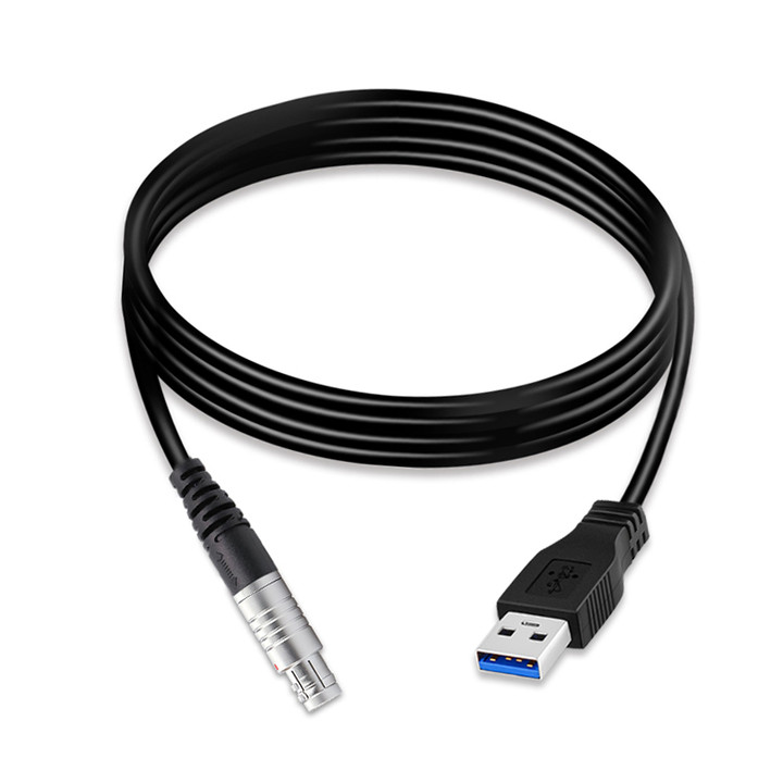
- Mobile cable plug terminals for temporary connection
- Low-voltage signal transmission terminals with low exposure risk
Male connectors are preferred for movable and pluggable terminals because their protruding structure is convenient for positioning and quick docking, adapting to frequent plug-in and pull-out operations.
3.2 Female Circular Connector Main Applications
Thanks to the enclosed socket protection structure, female connectors have outstanding safety and dustproof performance, and are widely used in fixed equipment ports, high-voltage circuits, and exposed environments:
- Equipment panel fixed interfaces, power distribution boxes, and control cabinet terminals
- High-voltage power supply circuits and live connection parts to avoid electric shock risks
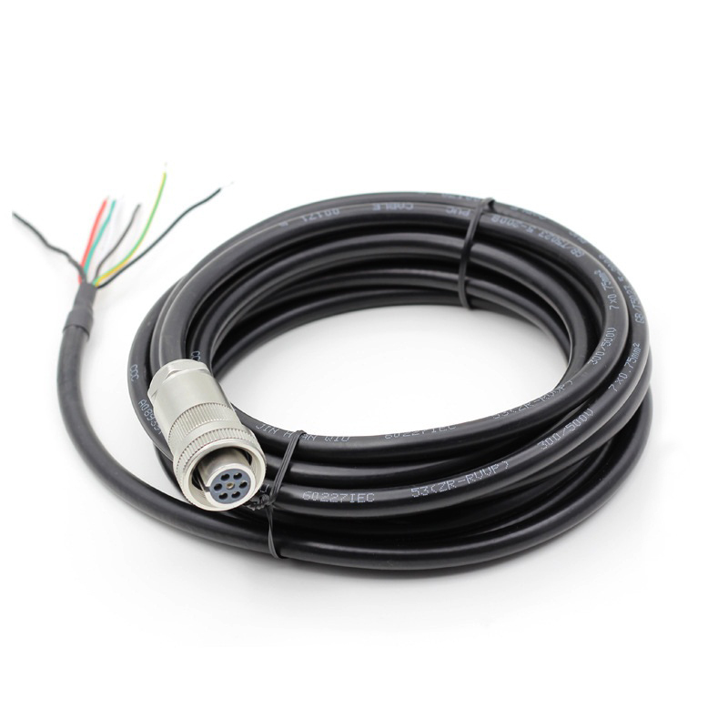
- Extension cables, wire harness terminals, and long-distance transmission lines
- Outdoor, dusty, humid and other harsh industrial environments
- Medical equipment, precision instruments requiring high safety and stability
A core safety principle in the industry: live parts must use female connectors. The recessed structure prevents accidental touch and short circuit caused by external debris, greatly improving system operation safety.
4. Key Selection Principles & Common Mistakes
Many connection failures are caused by incorrect selection of male and female connectors. Here are the core selection rules summarized for engineering use:
- Safety Priority: All exposed power ports and live connection terminals must adopt female sockets; movable plug terminals use male pins.
- Environment Adaptation: Outdoor and harsh environments prioritize female connectors for fixed ends to prevent dust and water from invading contacts.
- Wiring Accuracy: Distinguish clockwise male pin layout and counterclockwise female pin layout to avoid wrong wiring and signal reversal.
- Matching Consistency: Ensure the same pin count, locking type (threaded, bayonet, push-pull), and aperture specification for male and female mating pairs.
5. Conclusion
The essential difference between male and female circular connectors lies in pin layout direction and structural protection performance. Male connectors feature clockwise pin arrangement, exposed pins, and are suitable for movable plug-in terminals such as sensors and cable plugs. Female connectors adopt counterclockwise pin layout with enclosed protective sockets, which are safer and more durable, ideal for fixed equipment ports, high-voltage circuits, and harsh working environments.
Reasonable matching of male and female circular connectors not only ensures accurate signal and power transmission, but also effectively reduces equipment failure rates and maintenance costs. Whether for industrial automation, automotive wiring, medical equipment or audio system projects, mastering these differences is the basis for stable and reliable circuit connection.